ISO 6743-7 Family M · Metal removal · Forming · Cleaning · Protection

Metalworking Fluid Formulation —
from the cut to the cleaned component

We develop metalworking-fluid systems for cutting, grinding, honing, tapping, broaching, drawing, stamping, rolling, temporary corrosion protection and EDM. The work begins with the operation, alloy, tool, water, machine and downstream process; it does not begin by forcing every application into one soluble-oil recipe. The result is a controlled development package covering fluid-family selection, formulation IP, manufacturing SOP, qualification limits, field-trial design and shop-floor fluid management.
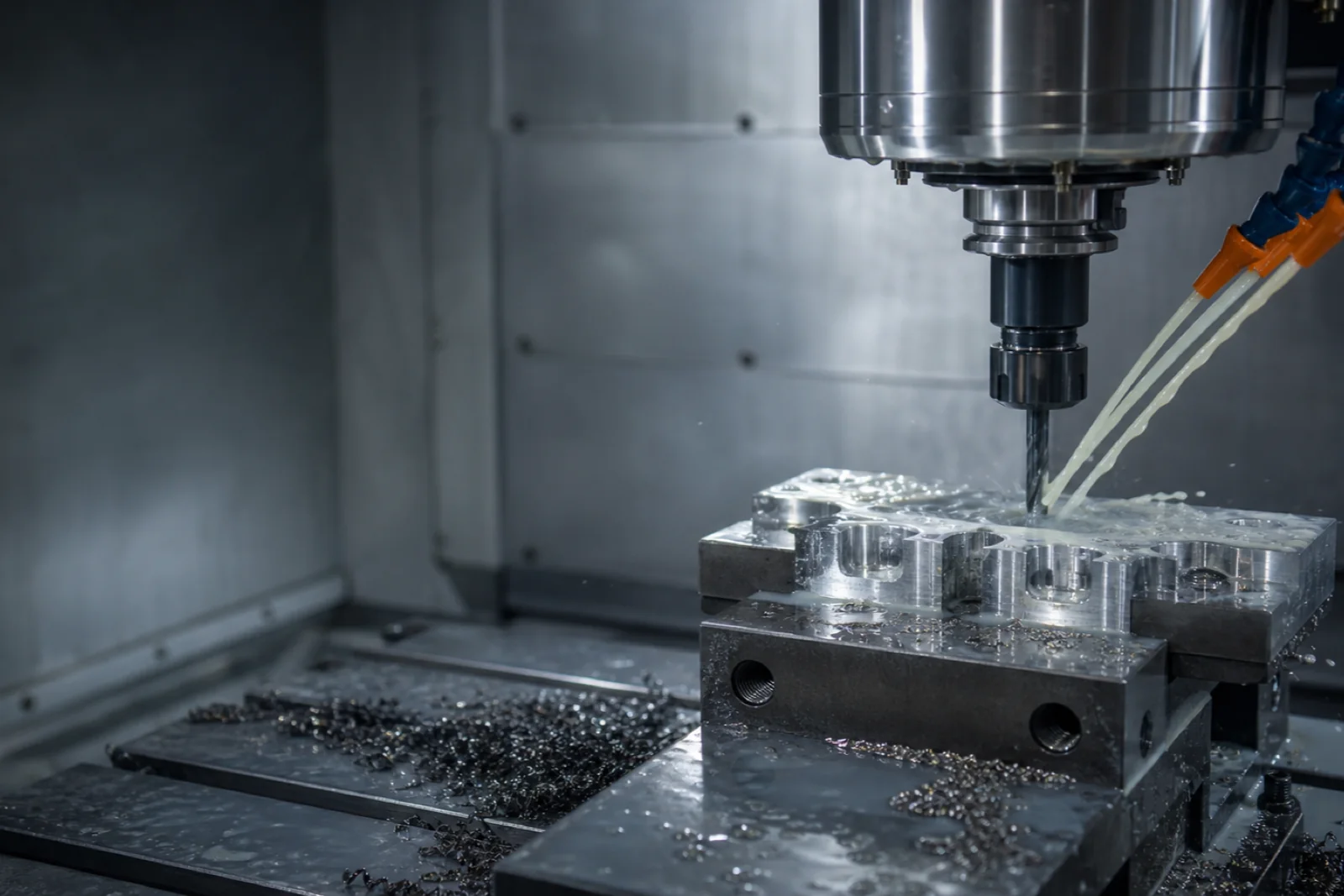
Enclosed CNC machining centre applying a controlled stream of pale metalworking coolant to a machined component
Service contextThe tool, workpiece, water and downstream process define the fluid system.
4
Core Removal-Fluid Families
3 Paths
Remove · Shape · Protect
Bench→Field
Qualification Sequence
Full IP
Controlled Client Handover
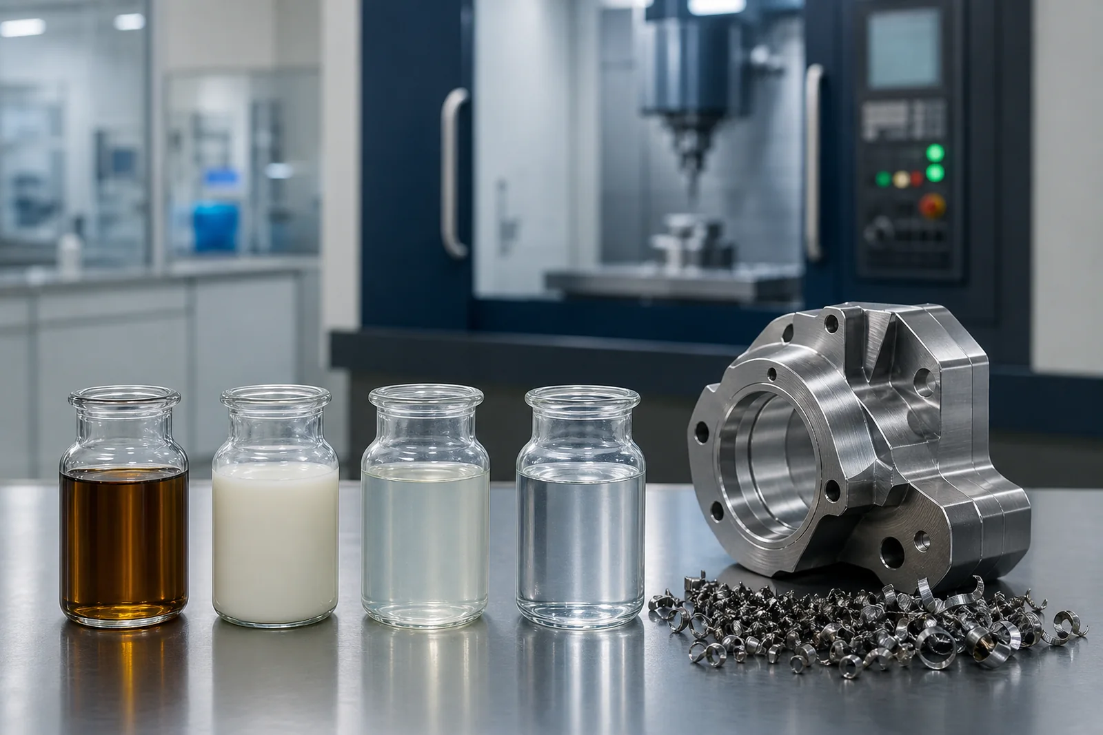
Neat, soluble, semi-synthetic and synthetic metalworking-fluid samples beside a precision-machined component
Fluid-family selection The visual comparison separates neat, soluble, semi-synthetic and synthetic routes before detailed formulation work begins.
  1. 01Operation and alloy
  2. 02Fluid-family selection
  3. 03Bench-to-field validation
The selection problem

Match the fluid to
the mechanism of work

A useful brief describes how metal is being removed or reshaped, what failure is unacceptable, and what happens to the component next. Cooling matters most in high-speed grinding; boundary lubricity and EP response dominate severe tapping or broaching; aluminium staining, cast-iron corrosion, foam and residue can rule out an otherwise strong system.

Development boundary: this page explains selection and validation logic. Exact ingredients, treat rates, suppliers, blend order and field-adjustment limits are issued only inside a scoped project and under NDA.
Enclosed CNC machining centre applying a controlled stream of pale metalworking coolant to a machined component
Tool–fluid interface The fluid must reach the active zone, carry heat and chips away, and remain controllable inside the machine enclosure.
REMOVE

Cutting and grinding fluids

Neat, soluble, semi-synthetic and synthetic systems for turning, milling, drilling, tapping, broaching, honing, sawing and grinding.

SHAPE

Forming and drawing lubricants

Oil-based, water-dilutable, evaporative and paste systems for stamping, deep drawing, tube drawing, wire drawing, rolling and cold heading.

PROTECT

Cleaning and temporary protection

In-process cleaners, dewatering fluids and rust preventives designed around the next wash, coating, assembly, storage or shipment stage.

Metalworking portfolio

Four removal-fluid families.
More than four product jobs.

MWF-A (NEAT)
Straight Cutting Oil
100% oil-based, no water. Mineral oil base (often Group I 100–500 SN) with sulphurised olefins, sulphurised fatty oils and chlorinated paraffins as EP additives. Used undiluted on heavy gear cutting, broaching, deep-hole drilling, and threading of stainless steel. ISO 6743-7 sub-codes MA, MB, MC depending on EP level.
Heavy Machining
MWF-B (SOLUBLE)
Conventional Soluble Oil
60–80% mineral oil emulsified with anionic (sulphonate) + non-ionic (ethoxylated alcohol) emulsifiers in water concentrate. Diluted 1:20–1:40 with water for milky white “coolant”. Workhorse for general turning, milling, drilling on carbon steel, cast iron and most non-ferrous. ISO 6743-7 sub-codes ME, MAE.
General Machining
MWF-C (SEMI-SYN)
Semi-Synthetic
10–30% mineral oil with synthetic surfactant package in water concentrate. Dilutes translucent (micro-emulsion droplets 0.1–1 µm). Better operator visibility, better cooling, better biological stability than soluble. Workhorse for CNC and modern flexible machining centres. ISO 6743-7 sub-code MAF.
CNC Standard
MWF-D (SYNTHETIC)
Fully Synthetic
No mineral oil. Water-soluble synthetic lubricants (polyalkylene glycols, alkanolamides, glycerol esters) in water. Dilutes clear. Excellent cooling, long sump life, best for grinding and high-speed light-load machining. Limited EP capability for heavy machining. ISO 6743-7 sub-code MAG.
Grinding / High-Speed
EDM
Electrical Discharge Machining
Specialised dielectric oil for EDM (sinker EDM). Highly refined hydrocarbon dielectric with low viscosity, low aromatic content. Different formulation discipline from cutting fluid — included here for completeness as the metalworking fluid family.
Specialty Dielectric
WIRE-DRAW
Wire Drawing Lubricant
Calcium soap + dry lubricant for steel wire drawing, copper wire drawing soluble emulsion. Adjacent product family with similar emulsifier chemistry but very different EP and surface-finish requirements.
Wire Industry
GRIND / HONE
Grinding & Honing Fluid
Low-foam, high-cooling systems designed to keep wheels and stones open, carry fines to filtration and protect ferrous surfaces without loading the abrasive. Synthetic or low-oil micro-emulsion routes are selected by finish, wheel, filtration and residue limits.
Precision Finish
TAP / BROACH
Severe-Operation Cutting Fluid
Boundary-lubricity and EP-led systems for high contact pressure and slow chip evacuation. The package changes with stainless steel, carbon steel, yellow metal, tool coating, smoke limits and the customer’s halogen policy.
High Load
STAMP / DRAW
Stamping & Deep-Drawing Fluid
Oil-based, water-dilutable, evaporative or paste lubricants that control galling, scoring and tearing as sheet flows across the die. Cleanability, weldability, coating compatibility and residue often decide the winning chemistry.
Sheet Metal
TUBE / COLD HEAD
Tube Drawing & Cold Forming
High-film-strength systems for tube reduction, cold heading, extrusion and difficult deformation. Substrate conversion coating, die material, reduction ratio and post-form cleaning must be designed as one process.
Severe Forming
CLEAN / PROTECT
In-Process Cleaner & Rust Preventive
Low-residue cleaners, dewatering fluids and temporary protective films prevent corrosion between machining, washing, inspection, assembly and shipment. Film removability and packaging environment are part of the brief.
Between Operations
ROLL / FORGE
Rolling & Forging Lubricant
Application-specific systems for roll bite control, die release, scale conditions and elevated tooling temperature. These programs require plant-specific trials because application method and carry-off dominate performance.
Bulk Metal Forming
Metalworking-Fluid Technical Library

Go deeper by fluid family,
process and field problem

Each page follows the same evidence path: operating window, formulation architecture, qualification gates, failure diagnosis and client-owned handover.

Water-mix chemistry architecture

What the concentrate
must make possible

Design blockWhat it controlsWhat can go wrong
Oil or synthetic lubricity carrierBoundary film, tool life and surface finishSmoke, residue, staining or insufficient load capacity
Emulsifier and hydrotrope systemDilution behaviour, droplet size and storage stabilityCreaming, splitting, hard-water soap or unstable concentrate
Corrosion and alkalinity systemFerrous protection, non-ferrous compatibility and reserve pHCast-iron rust, aluminium staining, residue or operator discomfort
Foam, microbial and contamination controlSump life, pumpability, air release and hygiene supportPersistent foam, odour, biomass, blocked filters or short sump life

Architecture only. Exact ingredients, treat rates, approved uses and suppliers are selected against the client brief, safety data and market regulations, then shared under NDA.

A refractometer does not read concentration directly unless the product-specific factor is known. The field-control band must be established for the actual fluid and water, then checked with pH, appearance, foam, tramp oil and microbial observations rather than relying on one number.

Family selection

Choose by trade-off,
not by appearance

FamilyPrimary strengthTypical constraintGood starting point when
Neat oilBoundary lubricity and severe-load protectionHeat removal, smoke, fire and housekeepingOperation severity dominates cooling
Soluble oilBalanced lubricity and coolingEmulsion and biological managementGeneral machining spans mixed operations
Semi-syntheticCooling, visibility and adaptable lubricityFoam and multimetal balanceModern CNC cells need one flexible fluid
SyntheticCooling, cleanliness and fines handlingBoundary load and residue sensitivityGrinding or light high-speed work dominates
Four laboratory samples showing neat oil, soluble oil, semi-synthetic and synthetic metalworking fluid families
Family comparison Neat oil, milky macro-emulsion, translucent micro-emulsion and clear synthetic fluid are different starting architectures, not quality grades.
Alloy and water compatibility

The same fluid can pass
on steel and fail on aluminium

Cast iron, carbon steel, stainless steel, aluminium alloys, copper and brass challenge different parts of the package. Water hardness and chloride load can change emulsion stability and corrosion behaviour before the fluid even reaches the machine.

Ferrous metals

Check chip corrosion, flash rust, stained swarf, carry-off film and protection after washing.

Aluminium

Screen staining and darkening across the actual alloy family, temperature and dwell time.

Yellow metals

Control copper and brass staining with chemistry selected for the customer’s alloy and process.

Plant water

Build dilution trials around measured hardness, chloride, conductivity and seasonal variability.

Performance Specifications

Build a qualification matrix
for the actual application

The values below are example development bands for an initial laboratory screen, not universal sales specifications. The client’s alloy, water, machine, fluid family, intended concentration and customer method define the final limits.

PropertyTest MethodSoluble TargetSemi-Synthetic TargetSynthetic Target
Appearance (5% in 200 ppm water)VisualMilky whiteTranslucentClear
Emulsion pH (5% working)pH meter8.8–9.39.0–9.59.0–9.5
Refractive index factorBrix refractometer1.2–1.51.0–1.20.8–1.0
Foam (after 5 min stirring, IS 1448 P-67)Stirring test<30 ml @ 1 min<20 ml @ 1 min<20 ml @ 1 min
Corrosion (chip / filter paper test)IP 287 / IS 1115No corrosion 4%No corrosion 3%No corrosion 3%
Hard water stability (5%, 400 ppm)VisualStable 24 hrStable 72 hrStable 7 days
Tramp oil rejection (5% hydraulic added)SeparationSeparates in 2 hrSeparates in 1 hrSeparates in 30 min
Sulphate ash (active sulphur)D8741.0–3.0%0.5–1.5%<0.5%
Falex pin-and-vee EP loadASTM D2670200–600 lbf150–500 lbf100–350 lbf
Microbial baseline (TVC)Dip slide<10³ CFU/ml<10³ CFU/ml<10³ CFU/ml
Patch corrosion (cast iron)IP 287Pass at 5%Pass at 4%Pass at 4%
Field proof matters: a fluid that looks stable in a beaker can still fail through aeration, filtration interaction, tramp-oil loading, carry-off, mist generation, residue or a downstream wash. Bench results set the gate for a controlled machine trial; they do not replace it.
Development process

Six gates from machine brief
to controlled handover

1
Operation, alloy and failure-mode brief
Capture machine type, cutting or forming severity, tool and coating, workpiece alloys, desired finish, current fluid, failure symptoms, downstream wash or coating, packaging and commercial target. Photographs, current TDS/SDS and a used-fluid sample shorten the diagnosis.
2
Plant-water and machine-system baseline
Measure water hardness, conductivity and chloride; map sump volume, pumps, pressure, aeration, filtration, tramp-oil ingress, temperature, enclosure and mist extraction. A fluid architecture that ignores these conditions may fail even when its bench chemistry is sound.
3
Architecture and raw-material screen
Select the fluid family and build competing routes around available raw materials, market regulations, SDS classification, alloy compatibility, cost and supply resilience. Every functional block receives a primary and practical alternative source where the brief permits.
4
Bench formulation and qualification screen
Prepare coded candidates and compare concentrate stability, dilution behaviour, hard-water tolerance, foam, corrosion, staining, residue, separation and relevant lubricity or load tests. Poor candidates stop here rather than consuming machine-trial time.
5
Controlled machine and sump trial
Agree a baseline and trial protocol before changing fluid: machine, part, tool, settings, dilution water, concentration band, top-up rule, filtration and observation cadence. Compare tool life, surface finish, temperature, foam, carry-off, residue, operator observations and used-fluid condition.
6
Scale-up, QC limits and IP handover
Translate the lab batch into the client’s vessel and mixing capability, verify a pilot or first commercial batch, then issue controlled formulation, manufacturing SOP, raw-material specifications, TDS/SDS inputs, COA limits, dilution and maintenance guide, and the agreed field-trial record.
Starting-point matrix

Operation first.
Then material and machine.

CNC TURNING
Carbide tooling, steel / cast iron
A semi-synthetic is often a useful starting point where cooling, chip flushing, visibility and mixed operations matter. Validate pump foam, alloy staining, tool life, residue, tramp-oil separation and actual plant water.
GRINDING
Surface, cylindrical, centerless
A low-foam synthetic or low-oil semi-synthetic can support cooling, wheel cleanliness and fines removal. Validate burn, wheel loading, filter compatibility, foam, cast-iron corrosion and part residue.
TAPPING / BROACHING
Hand tap, thread cutting, broaching
Neat or high-lubricity water-mix routes are screened by operation severity and machine design. Validate torque, tool life, weld marks, smoke, staining, residue and any halogen or sulphur restrictions.
DRILL / MILL
Job shop, vertical mill, drill press
Soluble or semi-synthetic fluids can balance cooling and lubricity for mixed job-shop work. The right choice depends on materials, sump size, filtration, water, maintenance discipline and the economics of concentrate use.
GEAR CUTTING
Hobbing, shaping, shaving
Neat oils are common starting points for hobbing and shaping when boundary load is high; some modern systems use high-lubricity water-mix fluids. Trial against tool wear, finish, smoke, carry-off and downstream cleaning.
ALUMINIUM / ALLOY
2W, 4W aluminium components
Synthetic or semi-synthetic routes may provide cleanliness and cooling, but the actual alloy must be screened for staining and etching. Validate across working concentration, temperature, dwell time and mixed-metal exposure.
Beyond cutting coolant

Forming-fluid development
is a system problem

A deep-drawing or stamping lubricant must create a stable film under pressure, help the sheet flow without galling, release from the die and still leave a component that can be washed, welded, coated or assembled. More lubricity is not automatically better if the residue defeats the next process.

Process severity

Draw ratio, reduction, contact pressure, speed, die geometry and tool material define the film-strength demand.

Application route

Roller, spray, dip, brush or recirculation changes viscosity, wetting, carry-off and consumption.

Surface outcome

Score, gall, tear, wrinkle, finish and dimensional repeatability become the trial acceptance criteria.

Next operation

Cleaning, welding, phosphating, painting, plating, bonding and storage set residue and removability limits.
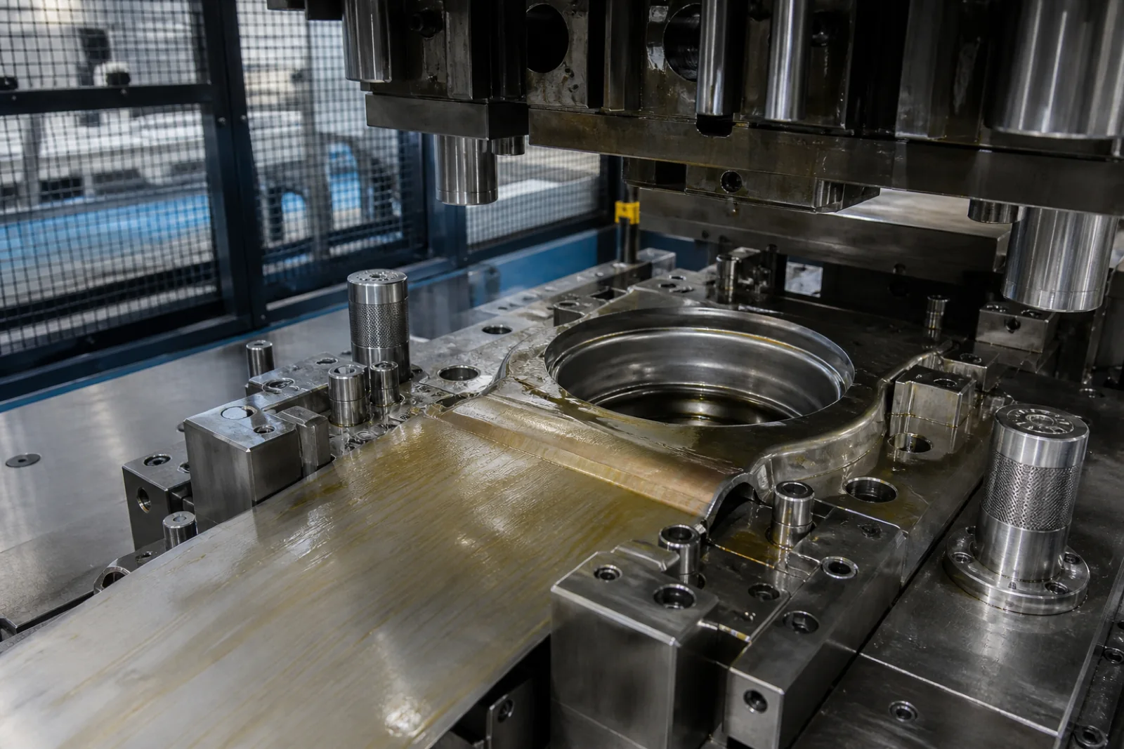
Guarded sheet-metal press tooling with a controlled film of amber forming lubricant on the die and workpiece
Stamping & deep drawing A controlled lubricant film supports material flow across the die; the downstream cleaning and coating route belongs in the original formulation brief.
Qualification and field trial

Prove the fluid at four levels.
Do not skip the baseline.

A
Concentrate release
Appearance, homogeneity, density, reserve alkalinity or acid value as relevant, storage stability, low-temperature behaviour and batch-to-batch fingerprint. These limits control what leaves the blending plant.
B
Dilution and compatibility
Prepare with the client’s water and application concentration. Check dilution order, emulsion appearance, foam, corrosion, alloy staining, tramp-oil behaviour, filter interaction and compatibility with machine oils, cleaners and legacy fluid residues.
C
Controlled machine trial
Freeze part, machine, tool, speeds, feeds and acceptance measurements. Compare against a documented baseline for tool life, cycle, surface finish, temperature, dimensional stability, smoke or mist, carry-off and consumption.
D
Sump or production follow-through
Track concentration with the product-specific refractometer factor, pH trend, appearance, odour, foam, tramp oil, microbial indicators, filter loading, top-up volume and operator observations. Agree corrective bands before the trial starts.
What the client receives

A production and field package,
not a one-page recipe

Controlled formulation & alternatives

Formula by weight, functional purpose of each component, approved raw-material grade, primary source and practical alternatives. Exact IP is transferred under the agreed NDA and project terms.

Manufacturing SOP & scale-up record

Charge order, mixing conditions, temperature and hold logic, filtration, in-process checks, release sequence and pilot-to-production observations matched to the client’s vessel.

Qualification matrix & COA limits

Concentrate, diluted-fluid and application tests with methods, acceptance limits, sample preparation, frequency and responsibility. External laboratory work is identified separately.

TDS, SDS inputs & use guidance

Technical-property table, application scope, dilution and make-up guidance, storage, incompatibilities, field-control bands and the ingredient data required for jurisdiction-specific hazard communication.

Field-trial protocol

Baseline, trial machine, part, tool, settings, measurements, review cadence, stop conditions and sign-off. This keeps commercial enthusiasm from replacing a controlled comparison.

Troubleshooting decision tree

First checks for foam, corrosion, staining, odour, instability, residue, short tool life, filter blockage and poor sump life, with clear boundaries for when a laboratory sample is required.

What we need from you
01OperationMachine, tool, speeds, feeds, pressure, filtration and application method.
02MaterialsAlloy grades, tool material/coating, seals and other fluids entering the system.
03Water & baselineWater report, sump size, current fluid, concentration, failures and used-fluid sample.
04Commercial boundaryTarget market, pack size, cost target, claims, restricted chemistry and launch volume.
Use-phase control

Fluid design does not replace
exposure and sump management

Water-mix fluids can support microbial growth, while machining can create aerosol and repeated skin contact. Enclosure, mist extraction, hygiene, fluid-quality monitoring, cleaning and health surveillance belong to the operating system around the product. Product selection and biocide strategy must follow current supplier labels and the rules of the market where the fluid will be sold and used.

Responsible boundary: Lubechem can design the formulation and fluid-management plan, but the site operator remains responsible for workplace risk assessment, engineering controls, PPE, health surveillance, waste handling and local legal compliance.
Questions & Answers

Frequently Asked About
Metalworking Fluid Formulation

What are the four core metal-removal fluid families?

Neat oils are used without water. Soluble oils form an oil-rich macro-emulsion in water. Semi-synthetics form a finer micro-emulsion with less oil. Synthetics contain no mineral oil and form a clear or near-clear solution. These are architectures, not a best-to-worst ranking; operation severity, cooling, alloy, water, machine and residue requirements determine the choice.

What concentration should a water-mix fluid run at?

There is no universal dilution ratio. The product developer sets an application band from corrosion, foam, lubricity, residue and field-trial results. A refractometer reading must be converted with the product-specific factor, and it should be interpreted with pH, appearance, tramp oil and fluid-condition observations.

How do you formulate for hard water?

We test candidate fluids in the actual plant water and in a deliberate hardness range. The emulsifier, hydrotrope and corrosion system is balanced to limit soap formation, instability, residue and loss of ferrous protection. Chloride and conductivity matter alongside hardness, so a complete water report is better than a single hardness value.

Can one fluid cover steel, cast iron and aluminium?

Sometimes, but only after mixed-metal screening. Ferrous corrosion, aluminium staining and yellow-metal reactivity respond differently to alkalinity and inhibitor chemistry. We test the actual alloy grades at working concentration and temperature, including realistic dwell and carry-off conditions.

How is biocide strategy selected?

Only from products approved for the intended market and use, at supplier-label conditions and after compatibility testing. The decision also considers concentrate preservation, in-use contamination, pH, temperature, exposure controls and customer restrictions. A biocide is not a substitute for correct make-up, tramp-oil removal, aeration control and sump cleaning.

Why does a metalworking-fluid sump develop odour or short life?

Common contributors include weak or drifting concentration, contaminated make-up water, stagnant zones, accumulated fines, tramp oil, poor aeration, incompatible cleaner or legacy-fluid residue, and inadequate cleaning before recharge. Diagnosis needs a sample, operating history and machine inspection rather than an automatic biocide top-up.

Can you develop forming, drawing and rust-preventive fluids too?

Yes. The scope includes stamping, deep drawing, tube and wire drawing, rolling, cold forming, in-process cleaners, dewatering fluids and temporary corrosion protection. These projects are qualified against the forming severity and the next operation, especially washing, welding, coating or storage.

What does the formulation project deliver?

The agreed package can include controlled formula and alternatives, manufacturing SOP, raw-material specifications, qualification matrix, COA limits, TDS and SDS inputs, dilution and fluid-management guide, field-trial protocol, scale-up support and IP handover. External laboratory or certification work is identified separately in the proposal.

Need a Metalworking Fluid
Designed for the actual process?

Share the operation, alloy, machine, tool, plant water, current-fluid TDS and failure or target. We will scope the formulation, qualification and field-trial work needed to reach a production-ready handover.